1. 常用画图元素
主要包含如下几种画图元素:
- 绘图类型
PDDON为不同类型的绘图提供了专属的定制化功能,各类型绘图具备各自特定的组件类型、连线类型、功能特性等。
不同类型的绘图可以根据用户的喜好自行选择更多可使用的组件库,也可以使用图片组件上传图片实现更丰富的图形组件。
如果你找不到合适的绘图类型,你可以新建freestyle类型的绘图,绘制更多自由风格的绘图。
* 基本类型* UML* 其他类型
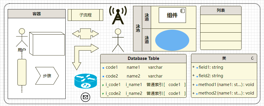
组件
PDDON提供非常丰富的组件库,包含各种图形组件、容器组件、功能组件等等,不同的组件的外观、业务含义、具备的功能特性不尽相同。 组件间可以通过连线进行连接,不同的组件具备各自的连接规则,用以控制组件是否允许引出/引入连线,可以通过属性面板查看组件信息。
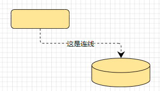
连线
用于建立组件之间的联系,以线条方式展示,可以设置不同样式的连线风格和箭头样式,可以添加描述信息。
线条
- 线条路径类型
连线路径由起始位置和结束位置确定,目前支持如下类型路径
xxxxxxxxxx* 直线* 曲线* 二次贝塞尔曲线* 直折线* 按长度分段直线
- 线条风格
可以选择PDDON预置的各种线条风格
- 线条样式
可以设置线条的颜色、宽度等等样式
- 描述信息
可以为连线添加描述信息,描述信息可以相对于连线位置:
xxxxxxxxxx* 开始位置* 中间位置: 默认使用中间位置描述信息* 结束位置
- 箭头
连线可以设置不同风格的箭头。控制起始、结束位置是否显示箭头,箭头是否需要填充,可以设置箭头大小、箭头形状、颜色等等
锚点
- 锚点附着在组件上,组件引入/引出连线时均需要选择具体位置的锚点进行连接。
- 组件在未选中状态时才允许连线操作。
- 鼠标访问组件时可以展示组件内预置锚点。
- 鼠标在组件区域内边缘处移动并点选可以触发自定义位置锚点。
- 锚点可以引出连线,亦可引入连线。
- 控制点
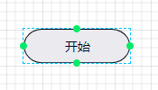
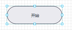
组件在选中状态下,组件周围会显示各个控制点,用于调制组件的尺寸大小。
2. 绘图模式
在大部分画图场景中,我们使用PDDON默认的智能模式进行绘图已经能够满足绝大部分需求,但是在某些特殊精细化绘图场景中,我们需要使用到其他绘图模式。主要包含如下几种绘图模式。
智能模式
同时可拖动组件、绘制连线,连线由鼠标悬停组件边缘触发。
移动模式
更易于对组件进行各种操作,如移动位置、调整尺寸等等,但不可连线操作。
画线模式
更易于绘制连线,但不可拖动组件位置。
拖动画布模式
可以使用抓手工具拖动画布视口位置,不可连线操作。
3. 常用操作
选中/取消选中组件
选中/取消选中组件方式有:
鼠标点击(CTL+鼠标点击为多选,否则为单选)
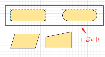
矩形选框(空白区域按住鼠标左键拖动)
未选中节点包含在区域内代表选中,否则为取消选中状态,矩形选框操作为多选模式
快捷键 (Ctrl + A)
右键菜单(选中组件/连线或取消选中)
单击画布空白区域即可取消所有选择
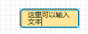
编辑组件/连线文本
双击组件、或连线可以进入编辑文本状态,点击右键选择编辑菜单亦可使组件进入编辑状态。
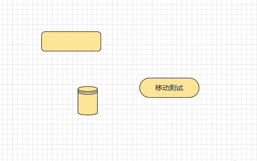
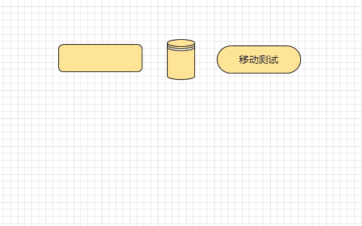
移动组件位置
单个组件移动:
光标移动到组件区域内,光标呈移动样式,按住鼠标左键向目标方向移动即可(容器组件光标需要移动到标题栏内或者近边框边缘处,以光标样式为指示进行操作即可)。容器类型组件移动会带动子组件一起移动。移动过程中会有辅助线参考对齐与自动吸附。
选择组件/分组移动:
可以选中多个目标组件或分组,按住鼠标左键拖动到目标位置即可。
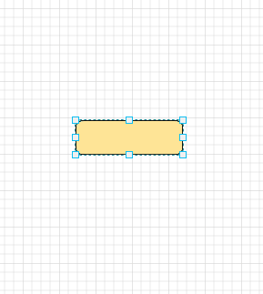
改变组件尺寸大小
选中单个组件时,可以显示组件控制点,鼠标左键按住并拖动可以调整组件大小。
连线操作
- 在智能模式下,鼠标悬停在组件边缘可引出连线,拉动到目标组件内释放引入连线,连线便创建成功。
- 在画线模式下,鼠标悬停在组件内可引出连线,拉动到目标组件内释放引入连线,连线便创建成功。
- 鼠标从组件边缘上锚点引出或引入,可以指定该锚点连线,否则系统根据组件位置关系自动计算连线锚点,并可以跟随组件位置变化而自动修改连接锚点。
撤销、恢复、复制、克隆、剪切、粘贴、删除等等
组件/连线均可以使用快捷键、右键菜单等方式进行常规操作,而且支持同页面不同绘图间进行操作。
旋转组件
- 先选中组件,再按住鼠标左键向目标方向拖动,会在组件中心点显示辅助线。
- 也可以使用右键菜单进行旋转或者取消旋转。
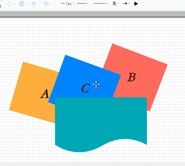
调整组件间层叠顺序
组件间区域有重叠时,可以使用右键菜单或工具栏层叠顺序调整功能,改变组件间垂直方向堆叠顺序。
调整画布尺寸
- 新增绘图时可以设置画图尺寸
- 组件新增、移动、尺寸调整时均可以自动调整画布尺寸
- 通过设置页可以修改当前绘图画布尺寸
- 通过视图菜单可以修改绘图画布尺寸
- 通过自动裁剪画布空白区域功能,可以裁剪掉绘图边缘多余空白区域
整体缩放画布
- 通过快捷键Ctrl + 鼠标滚轮进行快速缩放
- 通过工具栏进行缩放
- 通过视图菜单进行缩放
下载图片
可以将绘图导出为指定格式的图片,工具栏或菜单均可以操作。
导入导出绘图数据
您可以使用导入导出绘图数据功能,将您的绘图数据进行备份和恢复。
4. 完整绘图示例
经过本文的学习,相信你已经对PDDON有了一个初步的认识,现在一起来看看,我们如何使用PDDON进行绘图的吧!